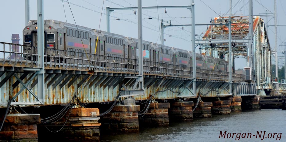
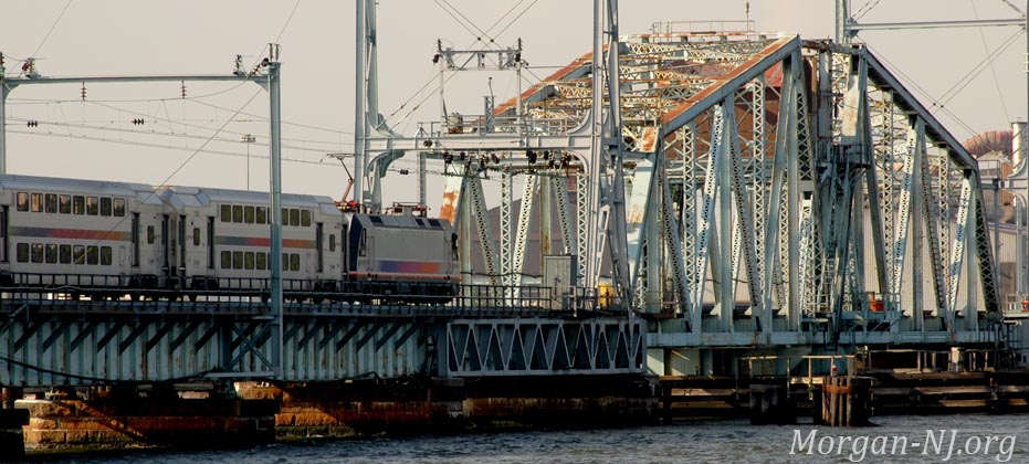
Northbound NJ TRANSIT train crossing the 1908 Raritan River Swing Drawbridge near the mouth of the Raritan River connecting South Amboy and Perth Amboy.
Morgan Momentum – NJ TRANSIT’s Raritan River Drawbridge
Hurricane Sandy’s great tidal surge in Raritan Bay during the early morning hours of Tuesday, October 27, 2012, wreaked havoc on both the New Jersey and Staten Island shore communities. Raritan Bay is shaped like a giant curved funnel with the apex situated at the mouth of the Raritan River – just north of Morgan (read about the 1887 Survey of Raritan Bay). As fate would have it, the full moon influenced high tide coincided with the peak time of Sandy’s fury. Because of Sandy’s left hook, water in the bay was pushed, i.e., blown by hurricane strength winds, westward from Sandy Hook 14 miles to the mouth of the Raritan River. The funnel effect caused the height of the water level to increase as the shores of the bay narrowed. Sitting right in this apex between South Amboy and Perth Amboy where the 13.6 foot surge of water flowed that early morning was NJ TRANSIT’s Raritan Bay Drawbridge.
The then 104-year old bridge sustained considerable damage caused by both the tidal forces as well as by an errant barge that was pushed into the bridge by the storm. Fortunately, the damage fell just short of a total catastrophe. Several of the pier capstones that support the approach span girder were dislodged or broken, and the motors that operate the bridge’s movable swing span were damaged but by far the biggest concern was the girder deck of the bridge having been moved 18 inches on its piers. According to NJ Transit Executive Director Steve Santoro, “If this bridge moved 24 inches during Sandy, it might have gone down, and we’d be standing here wondering how people would get to work.”
To get the bridge usable again, NJ TRANSIT entered into a $3,091,000.00 contract (plus five percent for contingencies) with Sparwick Contracting, Inc. of Lafayette, New Jersey, for the “repair of damaged supporting piers along the eastern approach spans of the existing Raritan River Draw.” These repairs involved lifting the bridge, aligning the girders and resetting them on the bearings, forming new reinforced concrete pier caps in place of the damaged stone pier caps, installing steel strapping to prevent any future movement of the masonry stone blocks, and pointing and grouting the pier masonry to fill in voids created from washouts.
The bridge was out of service for only three weeks – which was a pretty significant achievement. Kudos to NJ TRANSIT for making the repairs so quickly while also having to fix a lot of other Sandy induced problems, such as the washed out tracks in Morgan, and the repair of the Cheesequake Creek drawbridge at the same time.
However, the story doesn’t end – or begin – here.
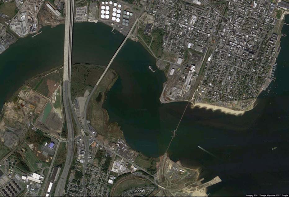
The Five Bridges at the Mouth of the Raritan River. Image Courtesy of Google Maps.
There are five bridges currently situated near the mouth of the Raritan River. In 1874, there were none. In east to west order (right to left), i.e., starting with the bridge closest to the bay, these bridges are:
- NJ TRANSIT Raritan River Drawbridge
- NJ State Highway Route 35 Victory Bridge
- NJ State Highway 9
- Thomas Alva Edison Memorial Bridge (northbound lanes)
- Ellis S. Vieser Memorial Bridge (southbound lanes)
- Garden State Parkway Governor Alfred E. Driscoll Bridge (widest bridge in the world by number of lanes).
This article will only discuss the railroad drawbridge; the others will be discussed in future additions to this web site.
The oldest bridge is the one closest to the bay and the one closest to sea level. This is NJ TRANSIT’s drawbridge which currently serves both railroad commuter and freight services:
- NJ TRANSIT’s North Jersey Coast Line – Which connects the 17 stations south of the bridge terminating at Bayhead with the 11 stations north of the bridge terminating at Penn Station in Manhattan. 19,200 daily commuters.
- Conrail – Which hauls two million tons of freight annually.
While it is the oldest, the current railroad drawbridge is not the first bridge to have been located at this spot. It is actually the second bridge and within a decade, it will be replaced by the third bridge. The first bridge, the one the current bridge replaced, was an engineering feat of its time and a world marvel.
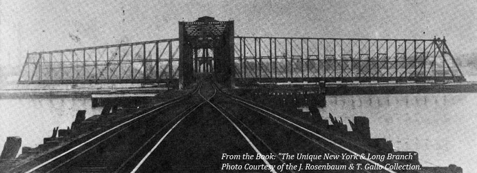
Rare Image of the Original 1875 New York & Long Branch Railroad Swing Drawbridge over the Raritan River Showing the Drawbridge in the Open Position. This bridge connects South Amboy and Perth Amboy. Image from the Book, “The Unique New York & Long Branch”. Used with Permission from the Joel Rosenbaum and Tom Gallo Collection.
The First Bridge
On April 8, 1868, just a few years after the end of the American Civil War, a railroad charter was granted for, according to the great book “The Unique New York and Long Branch,” by Don Wood, Joel Rosenbaum and Tom Gallo:
“… a rail line from South Amboy to any point on the line of the Raritan & Delaware Bay north of Eatontown, with the privilege of extending it through to Long Branch, said line to run by way of the villages of Matawan and Red Bank.”
Within a year later:
“A supplement to the charter dated March 30, 1869 called for extension across the Raritan River to Perth Amboy by bridge or ferry, which ever might be more convenient.”
Construction of the single track railroad line appears to have started quite a while later, after law suits and whatever, after a lease was signed on October 6, 1873 with the Central New Jersey Railroad. Part of the construction included building the largest of its kind bridge in the world over the Raritan River between South Amboy and Perth Amboy.
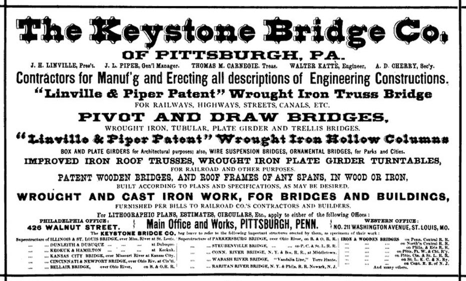
The first bridge to cross the Raritan River near its mouth with Raritan Bay, was built by Andrew Carnegie’s Keystone Bridge Company under the design and direction of Mr. J. H. Linville, formerly of the Pennsylvania Railroad. It was a wonder of engineering for its time and was the longest “swing” bridge in the world coming in at a whopping 472 feet – 32 feet longer than the previous record holder which spanned the Mississippi River in Louisiana, Missouri.
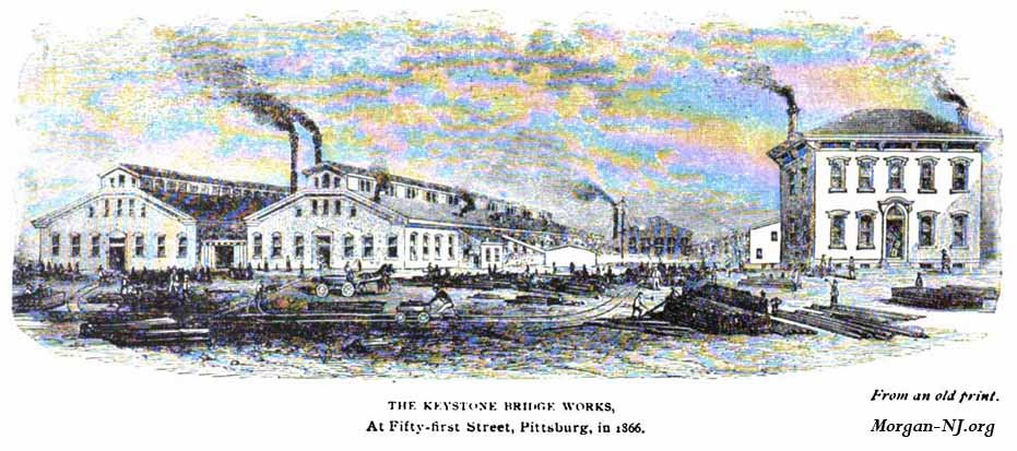
1866 Image of the Keystone Bridge Company
On Friday, Jun 25, 1875, two special excursion trains, one originating in Jersey City and one originating in Newark, carried invited guests of the New York and Long Branch Railroad in celebration of the official opening of the railroad the following week. Both trains stopped on the Perth Amboy side of the bridge to allow for the guests to witness, first-hand, the opening and closing of the longest drawbridge in the world. The most prominent of the dignitaries was the President of the United States, Ulysses S. Grant.
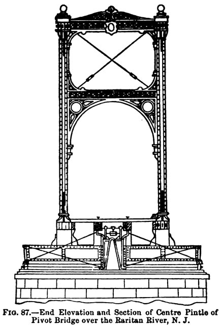
Center Pintle for the 1875 New York & Long Branch Railroad Swing Drawbridge over the Raritan River, i.e., the Center Pin which the Bridge Swings Around.
Matawan Journal June 26, 1875:
“Reaching the draw over the Raritan, a delay of some moments was taken, for the purpose of allowing the excursionists to get out and witness its workings. This grand structure is truly the mammoth triumph in civil engineering – the great bridge and the longest draw in the world, – opening and closing with its great wrought-iron jaws, the mouth of the Raritan river, whether the Pennsylvania Central “will or nill.” The draw at Louisiana, Mo, over the Mississippi river is 440 feet in length and was previous to this the largest ever made. The Raritan draw is 472 feet – 32 feet longer than its nearest compeer and weighs about 650 tons. It is supported on the “Pratt Truss Bridge” principle, the trusses measuring 40 feet in the center and tapering to 30 feet at the ends. It is 20 feet wide, sufficient for a double track. The cylinder or drum upon which the draw revolves is 30 feet in diameter, the cogs running upon a steel cog-wheel track, with the center working upon 16 cone pivots. The engine used for opening and closing the draw is a 20-horse power, and hydraulic lifts raise the whole structure between two and three inches before turning thus securing an exact fitting to the track at each end when it is swung to position for trains to cross. The total cost of the draw alone, independent of the trestle work connecting over the slope of the river to either shore, was about $125,000 and the six iron spans cost about $10,000 each, making the total of about $185,000. Four of the spans are 150 feet each, and the other two, 50 feet each. The entire iron work was furnished by the Keystone Bridge Company, Pittsburgh, PA.”
Immediately afterward, those same trains and President Ulysses S. Grant rode through Morgan on the newly laid track and over the newly built bridge over Cheesequake Creek!
Drawbridge Drawbacks
Even though the bridge at the time was only a few decades old, by the beginning of the 20th Century the original 1875 railroad drawbridge had many drawbacks. Aside from the usual maintenance problems which would creep up with having wooden piers immersed in salt water over the span of decades, railroad traffic was increasing and this bridge wasn’t going to be able to handle the projected needs for the growth for the two railroads (Pennsylvania Railroad and Jersey Central Lines) jointly leasing the road.
When the original railroad was constructed and the rails laid down in 1875, the route was composed of only a single track and thus the drawbridge was also just a single track wide. In 1882, a second parallel track was put in place along the whole route, i.e., “double track”, to allow for trains to go in both directions and no longer have to share the same track. There wasn’t a way however to put a second track on the Raritan River drawbridge to allow for two trains to simultaneously pass on the bridge. Indeed the bridge probably wasn’t engineered to support the weight of two trains to begin with.
An ingenious solution was put in place to accommodate the restriction of a single width drawbridge while still having parallel railroad tracks.
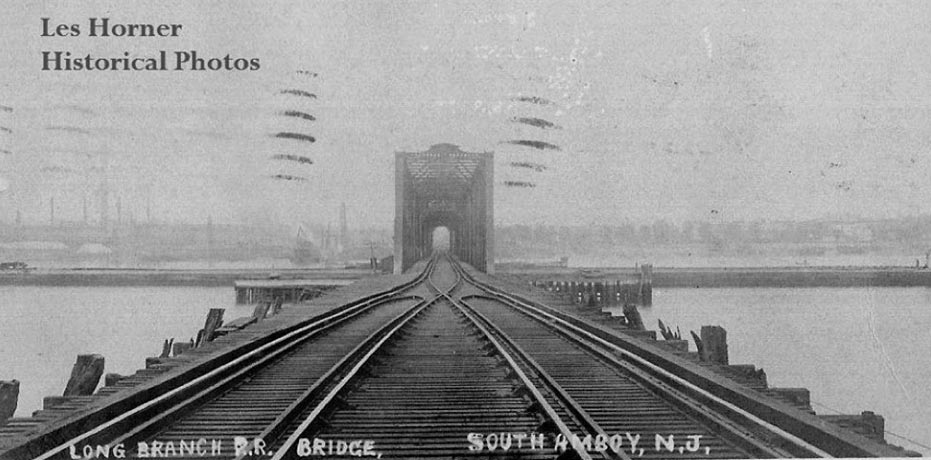
Rare Picture Post Card of the Original 1875 New York & Long Branch Railroad Swing Drawbridge over the Raritan River Showing the Drawbridge in the Closed Position. This bridge connects South Amboy and Perth Amboy. Image Courtesy of Les Horner.
If you look closely at the above image, you’ll see two tracks on the pier leading up to the drawbridge section but only one track on the drawbridge section itself. At first, you might think that a track “switch” had been used here but if you look closer, you’ll actually see it’s not just one track on the drawbridge section but actually two sets of tracks that overlap, or “interlace,” each other on the drawbridge section. Brilliant! Since the world’s longest drawbridge couldn’t have been widened, why not just squish the tracks together instead? That way there were still two parallel tracks without having to use a railroad switch. The problem with using a switch would have been that another switch would have had to have been located on the other side of the drawbridge. More importantly, a person continuously setting the positions of the switches would have been required, in the days before remote switching technology was available, which would have presented the possibility of a train being routed to the wrong way tracks on the other side of the bridge – the equivalent of getting on an automobile highway off ramp.
With this overlapped track, known as a “Gauntlet track,” the railroad eliminated the possibility of sending a train on the wrong tracks and the need for someone to always change the switch configurations. The width of the drawbridge imposed the restriction of being able to have only one train cross the bridge at a time anyway. At least with the gauntlet track, manual intervention using switches was eliminated. A southbound train required no effort from the bridge keeper to insure that after it crossed over the bridge it was still on the southbound tracks.
With the 1875 bridge, lengths and weights of trains were restricted as well. When the New York & Long Branch Railroad first opened, there were only seven passenger trains running per day across it in each direction (don’t know how many freight trains per day). As time went on, the continuous need for more capacity for both passenger and freight trains called out for a newer higher capacity bridge. In the days before automobiles were ubiquitous, summer was an especially busy time as the November 11, 1900 New York Times indicated:
As the road is leased jointly by the Pennsylvania and Jersey Central Railroads, and as these companies are increasing the number and size of their trains every season, better facilities are demanded. All the trains from Jersey City to the resorts on the Jersey coast pass over this bridge.
The solution came nearly 33 years after the first bridge opened when an all new bridge opened on April 21, 1908.
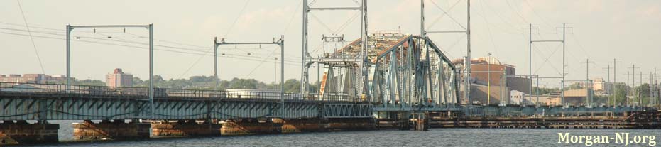
The Current Bridge over the River Raritan. 1908 NJ TRANSIT Raritan River Swing Drawbridge.
The Second Bridge (The Current Bridge)
Constructed for the then record price of one million dollars ($1,000,000), the replacement and current railroad bridge across the Raritan River has the following statistics:
- 2,919 foot long bridge system composed of:
- 936 feet – South Amboy to the south “Rest Pier*”
- 331 feet – Length of swing bridge (draw span)
- 1,652 feet – Perth Amboy to the north “Rest Pier*”
- 17 spans of 88 feet
- 11 spans of 100 feet
- 20 stone piers
- 8 feet higher above the river than the 1875 bridge
- 7,600 piles driven into the riverbed to support the piers
- 55 to 94 feet – range of the length of the piles
- Superstructure erected by the Pennsylvania Steel Company
* A “Rest Pier” is the pier containing a “surface” to support the end of the drawbridge when the drawbridge is in the “closed” position, i.e., when trains can cross over it. There are two “rest piers” for this (and probably any) type of swing drawbridge.
Building the Second Bridge (The Current Bridge)
Replacing an already existing structure, such as a bridge, comes with its own unique set of challenges. Trains still had to be able to keep running across the Raritan River with no “down time” – no doubt a phrase not used in 1908. For this bridge, it was also a race against time. The 1876 bridge was beyond the end of its life cycle (another computer related phrase likely not used in 1908) and large efforts were being made to keep the trains running as discussed in this April 22, 1908 New York Times article.
Location, Location, Location
For quite a while, finding information to help determine where the original 1875 bridge had been located in relation to the current bridge wasn’t forthcoming. On-line searches, the main research for someone in California doing research on something once located 3000 miles away and gone for 100 years, were not fruitful. In short, finding the answer was looking unlikely.
On-site, on both the South Amboy side and Perth Amboy side of the current bridge, there are no remaining piers or other obvious physical artifacts remaining. The only clues found were from comparing detailed maps from different decades looking for the relationship of the railroad bridge on the map to other fixed locations, such as the intersection of present day Broadway and Main Streets. Unfortunately the old maps found from the 1870s and later were understandably inaccurate. Still, a working theory was established. All that was needed was the right clue. Finally, a National Oceanographic and Atmospheric Administration (NOAA) map from 1911 was discovered which confirmed the placement theory – even though the map itself had a major imperfection regarding the track placement leading to the new bridge on the South Amboy side.
It was, however, the discovery of a 1908 Railroad Gazette article on-line (starting on page 630) which was beyond too good to be true. Here, finally, was an article which not only described the new bridge, in amazing detail and with drawings and photos, but also included a diagram showing precisely where the two bridges were located during that relatively short time period when they were both standing.
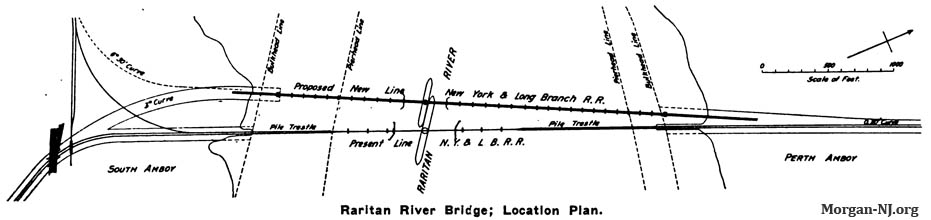
1908 Map Showing the Locations of the Original 1876 Bridge (bottom) and Current 1908 Bridge (top). Source: 1908 Railroad Gazette.
The above amazing diagram from the article shows that the original bridge was located just east of the current bridge, i.e., on the bay side!
More amazingly, one of the photos showed both bridges!
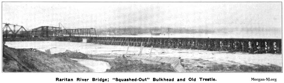
Rare Circa 1908 Image Showing the Original 1876 Bridge and Current 1908 Bridge.
Source: 1908 Railroad Gazette.
This article confirmed the findings to date but it also helped explain a number of other railroad related topics for that area of South Amboy. Unbelievable!
Here is a link to an image of the original 1876 bridge from the Rutgers University Community Repository which is part of the Rutgers University Special Collections Library.
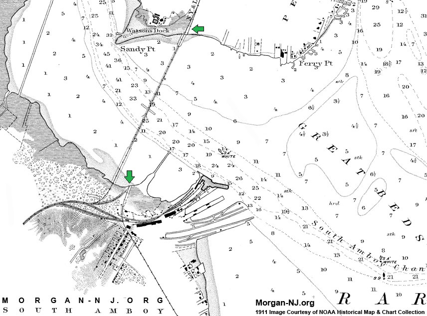
This historical 1911 NOAA map shows the current NJ TRANSIT Raritan River drawbridge linking South Amboy (bottom) with Perth Amboy (top). Vestiges of the remains of the track (right of way) from the original 1875 drawbridge appear just to the right of the bridge as is shown by the green arrows. Note that the map does not correctly show the railroad tracks on the South Amboy side connecting to the bridge. It only shows the Camden & Amboy Railroad branch (Pennsylvania Railroad at that time) connecting to the bridge. It doesn’t show the New York and Long Branch Railroad connecting to the bridge.
Track Curvature
The original curvature of the tracks from the South Amboy station to the approach to the original bridge was at an angle which was uncomfortably tight for trains going to the Jersey Shore on the New York and Long Branch Railroad side of the tracks. This limited the speeds in which trains could travel through this segment.
By locating the new bridge 200 feet west of the original bridge, the additional space allowed for the track curvature to go from the uncomfortable 7 degree angle curve to an apparently more comfortable 3 degree angle curve. While a seemingly insignificant change for a human, apparently it is significant for a train. According to the book “The Unique New York and Long Branch,” this change in curvature enabled “express trains to cut five minutes from their running length.”
Being that the bridge ultimately served two different railroads, the tracks which went to Camden on the Pennsylvania Railroad Line (the original Camden and Amboy Railroad right-of-way), were able to remain at their apparently comfortable 6 degree 30 minutes curvature. Note that originally the bridge did not connect to this line. This connection was likely added sometime in the 1880s, after a January 3, 1882 agreement between the New York & Long Branch Railroad, Pennsylvania Railroad, Central Railroad of New Jersey, and New Jersey Southern Railroad.
On the Perth Amboy side, the new bridge required the addition of a slightly acute angle to the tracks in order to connect the new bridge to the existing tracks leading to the Perth Amboy train station.

South Amboy Union Station, Circa early 1900s, Which Served the New York & Long Branch Railroad and Pennsylvania Railroad. Image Courtesy of Joyce Elyea.
Junction Station
A new South Amboy train station, called “South Amboy Junction Station”, was later built (exact date unknown) at the Y formed where the two tracks came together at the approach to the bridge. On the west side, at the top of the stairs, was the Camden & Amboy branch of the Pennsylvania Railroad. Via this line, passengers would be able to travel toward the southwestern part of New Jersey to Camden, across the Delaware River from Philadelphia.
On the east side, at the bottom of the stairs, was the New York & Long Branch branch, today’s NJ Transit’s North Jersey Coast line. By this route, passengers would be able to travel to Long Branch and south to the many ocean beach communities between Long Branch and Point Pleasant.
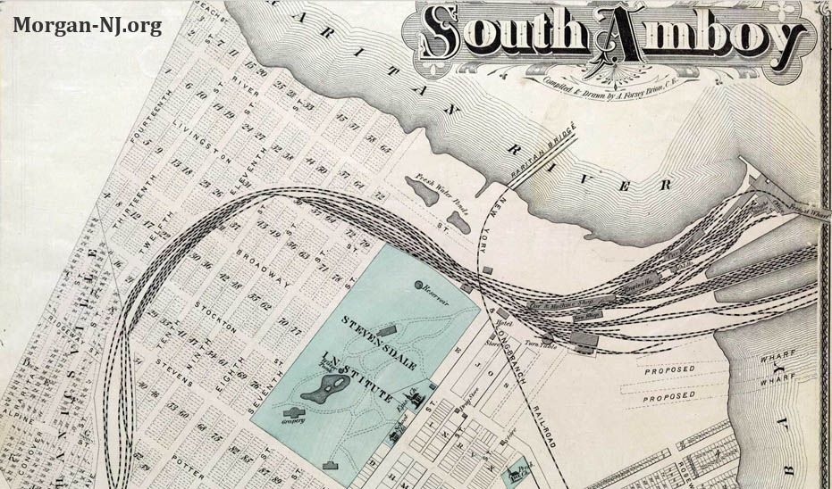
South Amboy Map Circa 1876.
Up until the completion of the Junction Station, Pennsylvania Railroad passengers had to endure the necessity of going around the curve on the South Amboy side of the bridge then backing the train up in order to get to the then station.
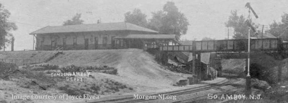
Camden and Amboy Railroad’s South Amboy Depot. Image Courtesy of Joyce Elyea.
While it isn’t totally clear which building on the map the above building was, or whether the C&A Depot shown in the image also handled passenger traffic, it is quite likely it is the building shown in the 1876 map just below the “Y” in the mistakenly spelled “NEW YORY” label along the railroad line coming from the bridge over the Raritan River.
South Amboy’s Junction Station was nearly destroyed on the evening of May 19, 1950 when four transfer lighters and several railroad cars loaded with 420 tons of explosives blew up some 2000 feet away at nearby Pier Number 4, commonly referred to as the “Powder Pier”. This second major catastrophe of munitions explosions in or near to South Amboy within a 32 year time period, with the first being the October 1918 T.A. Gillespie Loading Company in nearby Morgan, caused many basic changes in the area still shaping the city today. An example of one of these changes was the end of munitions facilities – manufacture, assembly, storage or shipping – near the populated areas in this part of New Jersey.
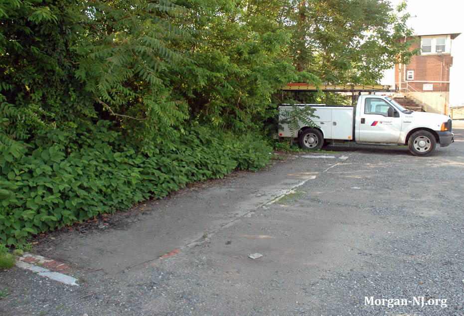
The remains of the base of the Junction Station in the area of the tracks between the old Camden and Amboy Branch and today’s NJ Transit’ North Jersey Coast Line with South Amboy’s surprisingly famous Essay Interlocking Tower in the background.
As with the exact date that it was built being unknown, the exact date when it was torn down is unknown as well. From a 2008 trip to the area, the foundation of the station seems to have still existed. The image of a brick inside with a concrete outside baseboard appears to match what was on the picture post card image.
This portion of the historical 1914 Ward Map of the City of Perth Amboy shows the path of the tracks (right of way) of the current NJ TRANSIT Raritan River drawbridge and the vestige of the path of the tracks leading to the original 1875 drawbridge (shown by the green arrow just west of Second Street). Image courtesy of Rutgers University Special Collections (http://mapmaker.rutgers.edu).
A New Bridge
On September 22, 2014, the Federal Transit Administration (FTA) announced federal disaster relief funding would be provided to NJ TRANSIT for five public transportation projects in the areas affected by Hurricane Sandy. The purpose of the funding is to allow the transportation infrastructure to become more resilient in order to withstand the impact of future natural disasters. In general, projects selected for resilience funding were required to demonstrate they would reduce the risk of damage to public transportation assets inflicted by future natural disasters. Emphasis was placed on a project’s ability to protect the most essential and vulnerable infrastructure, as well as effective collaboration and coordination among local and regional governments.
One of these five funded projects is designated as the “NJ TRANSIT North Jersey Coast Line (NJCL) Raritan River Bridge Replacement Project (River Draw).” In other words, the current 1908 railroad drawbridge connecting South Amboy and Perth Amboy will be replaced.
The FTA awards announced, totaling $3.59 billion, were spread across 40 projects with 90% of funds targeted for projects in New York and New Jersey where transit systems sustained the worst of the Hurricane Sandy storm damage. The remainder was distributed to projects in Connecticut, the District of Columbia, Massachusetts, New Hampshire, and Pennsylvania.
NJ TRANSIT was awarded $1,363,684,836 for 5 projects of which the Raritan River Bridge Replacement Project was awarded $446,312,465. According to NewJersey.com, the bridge construction is expected to cost $595 million (over a half a billion dollars – wow). New Jersey’s Transportation Trust Fund will provide the remaining $148.8 million. In February 2017, NJ Transit’s board approved spending $17.8 million on final bridge plans, with the design expected to begin in April 2017 and end in April 2018.
What Kind of Bridge?
NJ TRANSIT documents (Environmental Assessment & Appendicies) released in June 2017, described the analysis process leading up to the selection of the type of bridge which will cross the Raritan River between South Amboy and Perth Amboy for, likely, at least the next 100 years and most likely significantly more.
They laid out the following four project goals, each shown here with their expanded objectives:
- Improve resilience of the Raritan River Drawbridge to severe storms
- Improve bridge’s resistance to ocean surges
- Raise tracks and electrical mechanical systems above NJ TRANSIT’s Design Flood Elevation (2.5 feet above the Federal Emergency Management Agency’s Base Flood Elevation) to the extent practicable
- Design vulnerable components to better withstand saltwater and ocean surges
- Provide adequate structural capacity to comply with current code requirements
- Minimize loss of service on the North Jersey Coast Line during and following storm events
- Provide rail improvements that minimize service disruption and optimize operations
- Optimize design speeds for trains on the bridge, up to 60 miles per hour
- Avoid substantial compromises to existing North Jersey Coast Line timetables
- Accommodate heavier freight trains of 286,000 pounds and potentially up to 315,000 pounds
- Minimize capital and operating and maintenance costs
- Implement within a reasonable timeframe
- Avoid impacts to North jersey Coast Line and Conrail operations during construction
- Maintain and improve marine navigation beneath the bridge
- Minimize delays to marine traffic due to bridge malfunctions
- Widen channel to minimize the risk of collisions with marine vessels
- Enable the safer and faster passage of boats beneath the structure
- Avoid impacts to marine traffic during construction
- Minimize adverse impacts on the built and natural environment
- Avoid property acquisition to the maximum extent feasible
- Avoid, minimize, or mitigate adverse impacts on historic resources
- Avoid impacts on parklands, open space, natural features, and coastal waters
- Maintain access to nearby residences and businesses during construction
- Minimize construction impacts to the extent feasible
With these four goals in mind, they derived three different alternatives regarding the complete bridge system:
- No Action Alternative
- Keep the current bridge as it is and only perform maintenance when issues arise
- Rehabilitation Alternative
- Upgrade the current existing bridge and spans which connect South Amboy and Perth Amboy to meet current standards and requirements for storm resilience
- Bridge Replacement Alternatives
- New bridge would be located within the footprint of the existing bridge
- New non-movable bridge (“fixed span”) located either to the east or west of the existing bridge’s location
- New moveable span bridge to the west of the existing bridge’s location
- New moveable span bridge to the east (bay side) of the existing bridge’s location
- New moveable span bridge to the west of the existing bridge’s location with the center span perpendicular to the navigation channel (which is some 10 degrees off axis from the current bridge and river)
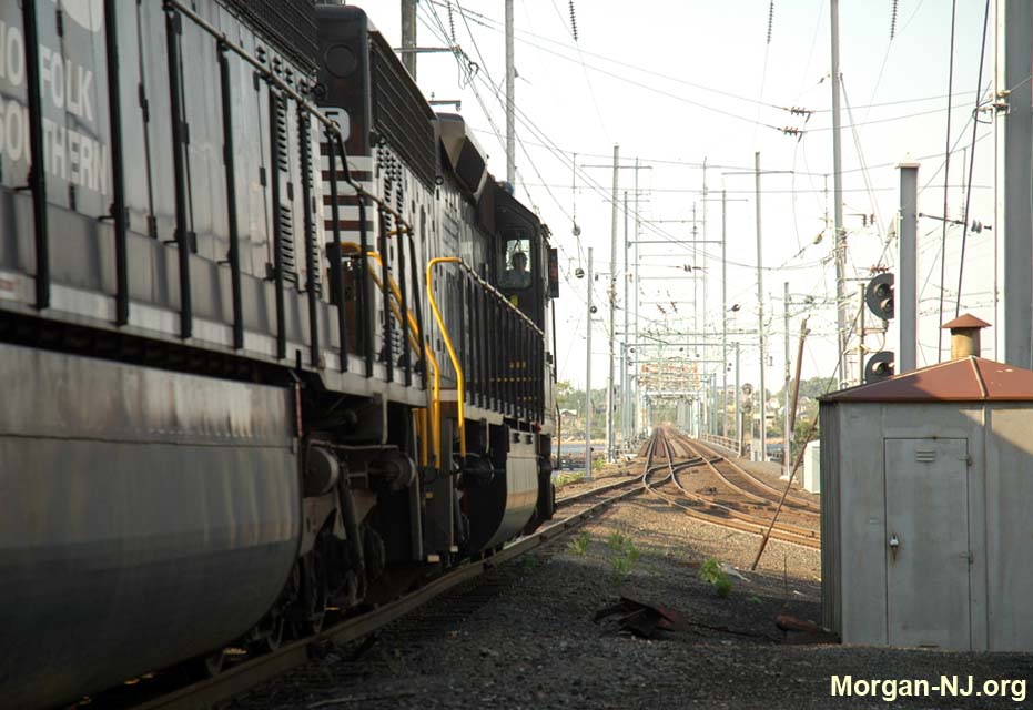
Norfolk Southern Railroad Engine Entering the 1908 Raritan River Bridge from the Old Camden and Amboy Right of Way in South Amboy, New Jersey.
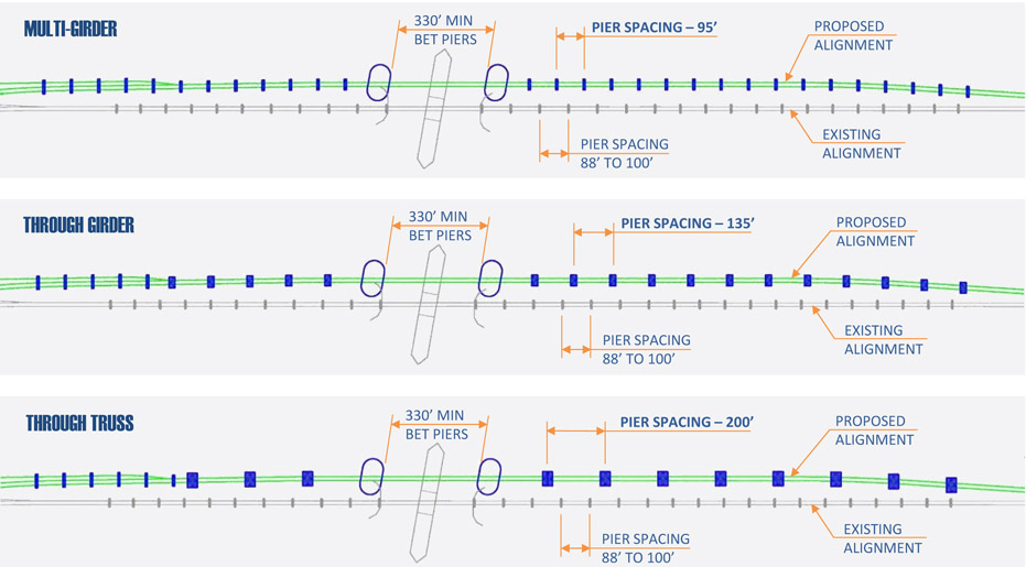
For all of the three movable bridge replacement alternatives, new spans holding the two sets of railroad tracks between the South Amboy side to the bridge and the bridge to the Perth Amboy side will be required. There were three options identified for this as well which are probably very clear to a mechanical engineer but not the rest of us:
- Use of steel multi-girders, which generally require relatively small bridge piers located approximately 95 feet apart
- Use of steel through-girders, which generally require larger bridge piers located approximately 140 feet apart
- Use of steel through-trusses, which generally require relatively large bridge piers located approximately 190 feet apart
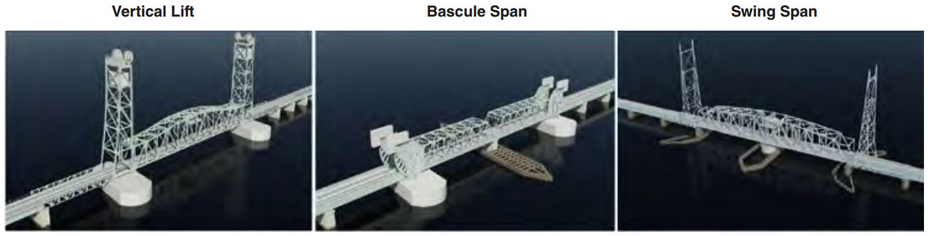
Finally, there were three options for the actual bridge itself.
- Swing Bridge – similar to the existing bridge
- Bascule Bridge – either a single leaf bascule or double leaf bascules
- Vertical Lift Bridge
Remember that the whole system, i.e., the spans leading to the bridge from the land and the bridge itself, has to satisfy the following criteria:
- Closed position of the bridge needs to be higher than the current height of the existing bridge and as high as possible with the following constraints:
- The elevations of the existing South Amboy station and the Perth Amboy station cannot change.
- The grade of the tracks (i.e., up or down angle) cannot be greater than 1.5 percent. This is a limitation imposed by the requirement to support freight train operations.
This height requirement is primarily to support being above future flooding events with the fortunate by-product of supporting the passageway of more watercraft without the necessity of opening the bridge.
- Bridge needs to be as high above the “Federal Emergency Management Agency (FEMA) Base Flood Elevation (BFE)” as is practical
- Vertical clearance = 110 feet, which is the same height as the Victory Bridge but less than the existing constraint which are cables 140 feet above the river.
- Trains should be able to travel 60 miles per hour leading up to and over the bridge
- The bridge’s operating machinery, e.g., motors to move the bridge, etc., must be above any height which would be subject to potential immersion into salt water
- Bridge system must accommodate freight rail cars weighing up to 315,000 pounds as is called for in the New Jersey Statewide Freight Rail Strategic Plan (2014)
The Decisions
Which Alternative?
In order to help determine which of the seven alternatives should be chosen, the below matrix was used.
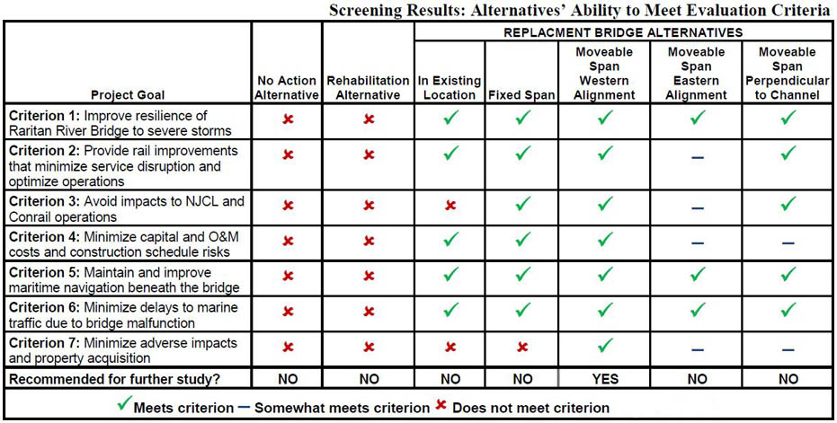
As can be seen, the only alternative which satisfies all of the Project Goals is the “Movable Span Western Alignment” one. This means the new bridge would be located between the current railroad bridge and the Victory Bridge.
The final two questions are:
- What type of “superstructure” leading to/from the bridge will be built?
- What type of bridge will be built?
This next portion i.e., describing the different superstructure and bridge types, is from section A.8 of the Raritan River Bridge Replacement Environmental Assessment document.
RARITAN RIVER BRIDGE REPLACEMENT PROJECT
Which Superstructure Type?
Steel multi-girders would accommodate relatively short spans (95 feet) and require the most bridge piers of relatively small size. Steel multi-girders would provide a redundant and reliable superstructure system, at relatively low cost. Steel multi-girders are easy to maintain, typically requiring localized steel repairs and/or replacement of a girder. Due to the redundant nature of this system, repairs are relatively easy to make since temporary support systems would typically not be required. Steel multigirders can be shop fabricated in any length and transported to the site relatively easily. Structural resiliency would be provided by designing the superstructure and bearings with adequate structural resistance to the forces imposed by a storm. Steel multi-girders would replicate the appearance of the existing bridge.
Steel through-girders would accommodate longer spans (approximately 140 feet) than the steel multigirder option and require fewer, but larger bridge piers, at a higher cost. Steel through-girders provide for a reliable structure but maintenance needs are more complicated since temporary support systems would be required to replace individual girders. Steel through-girders can also be shop-fabricated and transported to the site relatively easily.
Steel through trusses would accommodate the longest spans (approximately 190 feet) and require the fewest and largest bridge piers at the highest cost. Comparatively, this option requires significant maintenance throughout the structures lifespan. Unless site constraints dictate the use of a long span, one of the other options is usually chosen over the steel through truss option due to the significant inspection and maintenance requirements.
Potential impacts on natural resources would not be appreciably different under any of these options. The total cubic yards of fill in the river related to the installation of bridge piers would be similar under each option.
As a result of these considerations, steel multi-girders are NJ TRANSIT’s preferred option for the superstructure.
Source: NJ Transit
Which Bridge Type?
The next, and final question is what type of bridge will be built? There are essentially three types of bridges which could be built for this type of purpose.
Each bridge type has its pluses and minuses. As we know, the first two railroad bridges between South Amboy and Perth Amboy were swing type of bridges. If you examine the NJ Transit documents, you’ll see just how many things were taken into consideration which ultimately lead to the final decision. This next portion, i.e., describing the different bridge types, is from Appendix A, section A.8.2 of the Raritan River Bridge Replacement Environmental Assessment document.
SWING BRIDGE
The existing moveable bridge is a swing bridge, which rotates around a center pivot pier to allow vessels to pass beneath the bridge. A major issue with constructing another swing bridge at the Raritan River Bridge location is the need to construct a new center pivot pier within the existing navigation channel, which would require closing off half of the channel during construction. In addition, this moveable span option would require a 210-foot distance between the existing and new bridges, since the new and existing swing bridges would be in place at the same time during testing and commissioning of the new bridge. During this period, the new swing bridge would have to be opened simultaneously with the existing bridge. Simultaneous operations would be at a slower than normal speed to ensure clearance, which would impact rail operations and marine navigation. A swing bridge also requires more maintenance and associated costs compared to the other moveable span options due its mechanical components, which would be located below track level. Watertight machinery enclosures would need to be incorporated into the design to ensure adequate flood resiliency. Finally, the swing bridge would require a center pivot pier with an extensive fender system. The new piers and fender system could be designed to follow the alignment of the channel, thus eliminating the channel taper effect that currently exists. However, this bridge type option would still divide the channel into two, and provide only marginal benefits to marine navigation.
BASCULE BRIDGE
A bascule bridge is operated by rotating about a transverse horizontal axis on one or both sides of the navigation channel. Because of the size of the channel and the relatively low vertical profile of the bridge, one single bascule is not feasible. Therefore, two single-leaf bascules which share a common center rest pier would be required. Similar to the swing bridge, this option would require closure of one half of the navigation channel during construction and would provide only marginal benefits to marine navigation.
VERTICAL LIFT BRIDGE
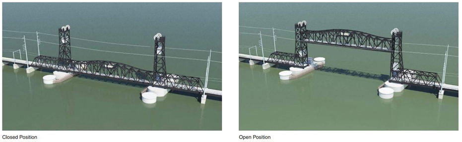
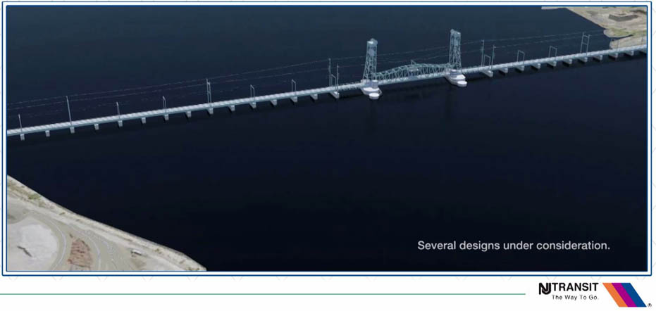
A vertical lift bridge operates by raising and lowering the main span through the use of lifting apparatus situated in towers located on each side of the main span. This option is the most resilient since the mechanical equipment would be located well above NJ TRANSIT’s Design Flood Evaluation criteria. Unlike the swing and bascule span options, the vertical lift design does not rely on rotation of the main span to clear the navigation channel. This option would result in long-term improvements for marine navigation since it would accommodate unobstructed passage of the entire width of the 300-foot-wide channel. During testing and commissioning the vertical lift bridge would be left in the open position, allowing the existing swing bridge to operate freely. Once the vertical lift bridge is in operation, but prior to demolition of the existing bridge, the two bridges would operate in succession, which would have the least impact on railroad operations and marine navigation.
As a result of these considerations, a vertical lift bridge is NJ TRANSIT’s preferred option for the bridge type.
The Bridge Itself
And so the winner is the vertical lift bridge. What are the specifics of bridge to be built with this decision? Section S.2.2.1 of the Environmental Assessment report addresses this:
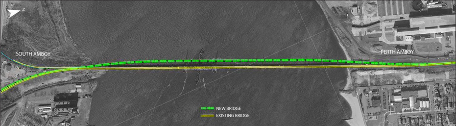
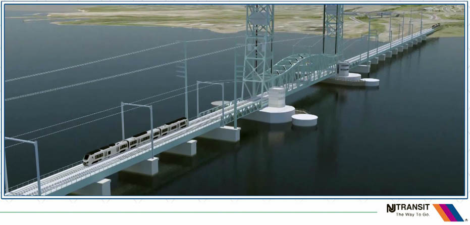
The new bridge will consist of a steel multi-girder superstructure, with bridge pier spacing similar to that of the existing bridge at approximately 95 feet apart. The new bridge piers will consist of long narrow caissons with concrete caps at the top. The main span will be a vertical lift to permit the passage of boats beneath the structure. The new bridge will be approximately 37 feet wide (an increase from the existing 22-foot width), to allow space for two tracks that are at least 14 feet apart, measured center line to center line, and two 4-foot-wide maintenance walkways on either side. The approach track and the fixed spans of the bridge will have continuous welded rail on a ballasted deck. The proposed new bridge will be parallel to and west of the existing bridge.
 RARITAN RIVER BRIDGE REPLACEMENT PROJECT
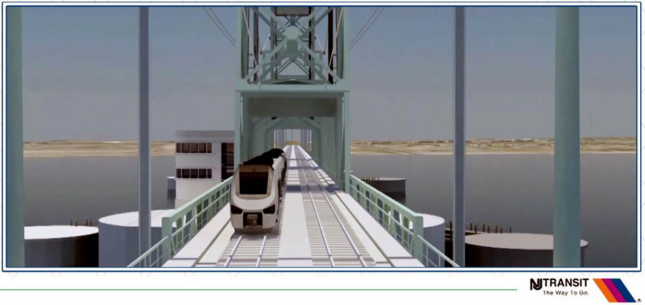
The alignment will be close to the existing bridge, to minimize the upland areas affected by the landside approach tracks. Based on conceptual design information, the new alignment is approximately 50 feet from the existing bridge measured from edge to edge, depending on further engineering. This allows construction almost entirely within NJ TRANSIT’s existing right-of-way for the North Jersey Coast Line. One of the key goals for the proposed project is to raise the bridge deck above the NJ TRANSIT Design Flood Elevation criterion to the extent practicable, to increase resilience to flooding. The new bridge deck will be approximately ten feet higher than the existing bridge deck (18 feet higher than mean high water), which will raise the track bed to higher than the NJ TRANSIT Design Flood Elevation, which is 2.5 feet above the Federal Emergency Management Agency (FEMA) Base Flood Elevation (BFE). Vertical lift bridges operate by moving a center span vertically to allow the passage of vessels underneath.
The center span operates along two towers that house the counterweights required to raise and lower the moveable span. The mechanical equipment will be located on the towers and the moveable span will be well above the FEMA BFE. With the new bridge, the navigation channel in the Raritan River will remain in its existing location and no river bottom dredging will be required. Currently, the navigation channel at the existing bridge is bifurcated into two narrow channels due to the swing span that revolves around a center pier. The vertical lift span will allow boats to pass beneath the bridge within an unimpeded area of approximately 300 feet, which is the full width of the navigation channel. The vertical lift span will provide for a vertical clearance of 110 feet.
The new bridge will have new overhead catenary wires and traction power cables, supported on independent monopoles approximately as high as the bridge towers.
If plans are approved near to the time of this writing, construction is estimated to start in the spring of 2019 and take four to five years to complete.
 We can see how the cost of replacing old infrastructure becomes massively more expensive as time moves on. Consider the Goethals Bridge replacement, where a bridge which opened in 1928 for the cost of $7.2 million was replaced by two bridges, with the first opening in 2017, for the whooping cost of $1.5 billion. New railroad tunnels are needed under the Hudson River connecting Jersey City with Manhattan with a projected price tag in excess of $20 billion.
 It is interesting to note that the current bridge, when opened in 1908 was per some sources the most expensive bridge built to date. Its cost was about $1,000,000. The 1908 bridge replaced a bridge which opened in 1876 which cost $185,000. This next bridge will cost $595 million!
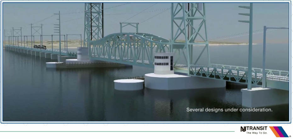
This NJ TRANSIT site contains a video discussing the new bridge and from which some of the photos here were obtained.
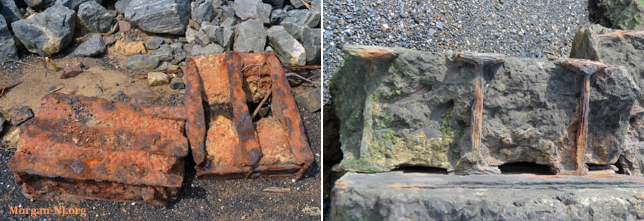
A Curiosity
A 2013 visit to South Amboy at the water line, in between the railroad tracks and the shuttered E. H. Werner Power Plant, revealed a pile of very old and rusted blocks of metal I-beams encased in concrete. They felt very much like something from the Victorian era. Not knowing the history of that immediate area at that time, no explanation was obvious.
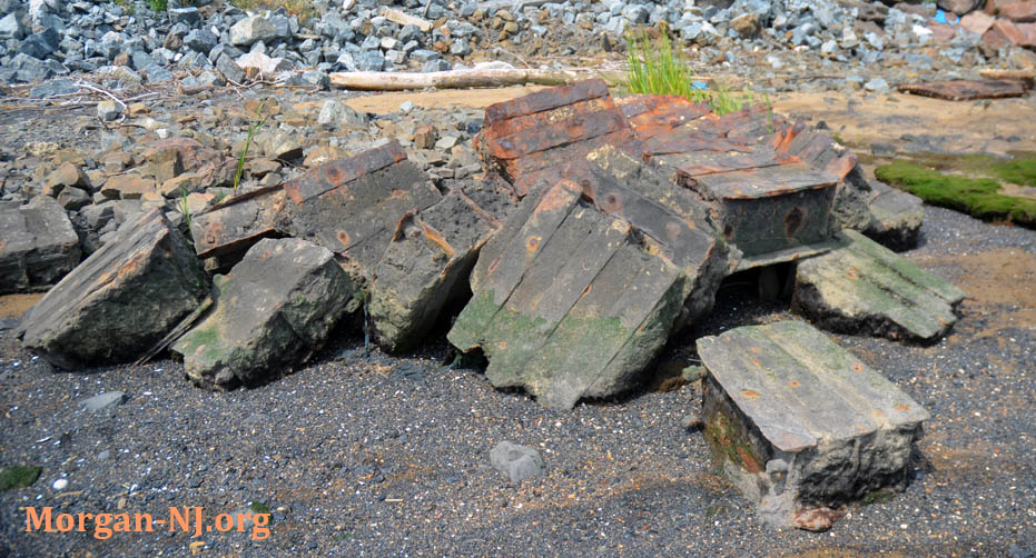
Knowing now that the original bridge was located where the subsequently demolished power plant was located – a few dozens of yards from the rubble pile, could it be possible that these blocks of metal in concrete actually were from the Victorian era because they actually were part of original 1876 railroad bridge?
We may never know for certain but it certainly seems plausible and kind of fun to think about.
Originally posted on August, 6, 2017.